
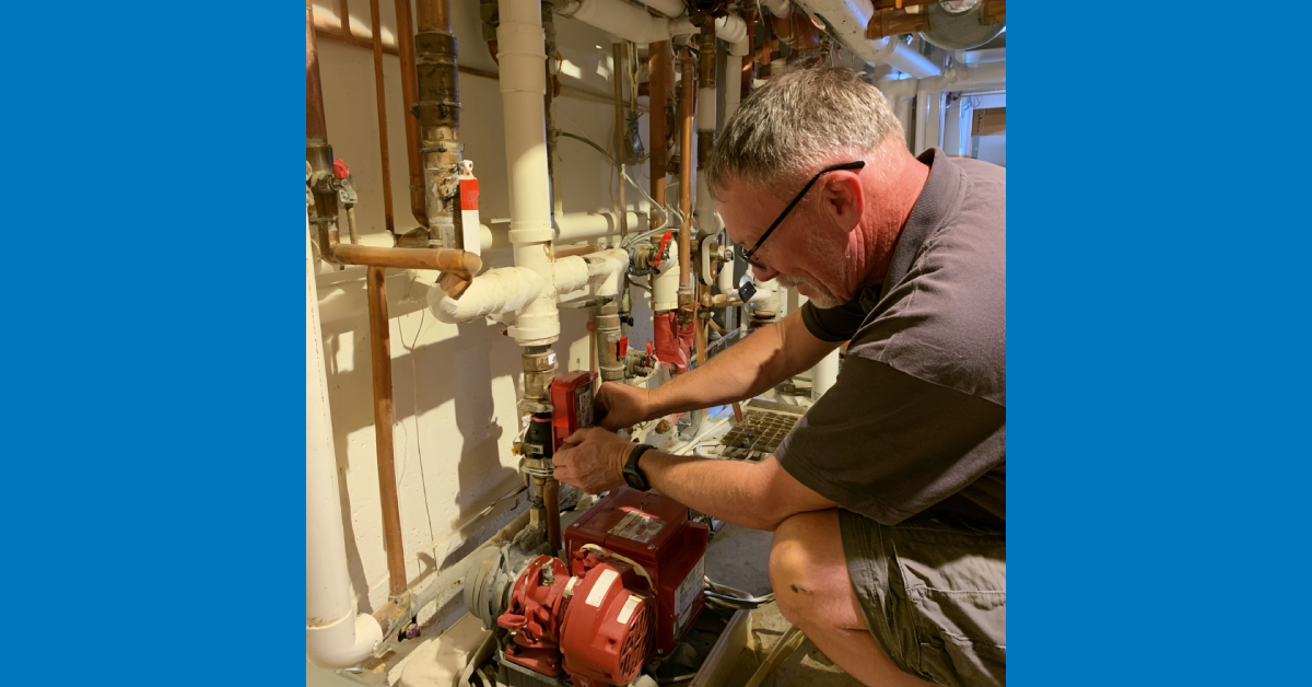
Variable flow system startup: what to verify on the pump system before the heating season load hits.
A variable flow hydronic system that was commissioned correctly and has been operating without problems does not start heating season in the same condition it was in at the end of last heating season. Setpoints drift. Drive parameters get changed during troubleshooting and not restored. Sensors accumulate calibration error. Control valves that were operating correctly at the end of April may have sticking actuators by September after sitting largely idle through the summer cooling season.
The pre-season pump check covers the mechanical condition of the pump equipment. The variable flow startup check covers something different: the system’s ability to deliver the right flow at the right pressure to the right places in response to actual building load. A pump that passes the mechanical inspection can still be part of a variable flow system that performs poorly in heating season because the controls, sensors, and setpoints have not been verified.
Differential pressure sensor calibration and location verification
The differential pressure sensor is the most important component in a variable flow system from a performance standpoint and the component whose condition is most rarely verified before heating season. The sensor controls the pump speed. A sensor that is reading incorrectly causes the pump to run at the wrong speed regardless of how correctly everything else in the system is set up.
Before heating season, confirm that the differential pressure sensor is reading correctly by comparing its output against a calibrated reference measurement at the same location. A sensor that has drifted by even a few PSI produces pump speed errors that accumulate into significant flow and pressure deviations at the terminal units.
Also confirm that the sensor is installed at the correct location. The correct location is at the most hydraulically remote terminal unit in the system. A sensor that has been moved, added, or replaced since original commissioning may be at a location that is not the most remote point, causing the pump to respond to conditions at a point that already has adequate pressure while the actual most remote unit is underserved.
Minimum flow bypass verification
The minimum flow bypass maintains the minimum flow required by the primary equipment when all terminal unit control valves are nearly closed. Before heating season, verify that the bypass valve is opening at the correct differential pressure setpoint and that the bypass flow rate is sufficient to maintain minimum flow requirements for the boiler or chiller it protects.
A bypass valve that has been manually adjusted, that has a failed actuator, or whose setpoint has drifted will either allow the primary equipment to operate below its minimum flow requirement, which risks equipment damage, or will bypass flow that should be serving terminal units, which reduces the effective capacity of the system. Test the bypass by closing terminal unit control valves progressively until the bypass opens and confirming that the bypass flow rate meets the minimum flow specification.
Variable speed drive setpoint review
Variable speed drives on hydronic pumps accumulate parameter changes during the operating season. A technician troubleshooting a noise complaint may have reduced the maximum speed. A controls contractor addressing a pressure complaint may have adjusted the PID parameters. A power event may have reset parameters to factory defaults. Before heating season, connect to each drive and confirm that the parameters match the commissioning documentation for the system.
Key parameters to verify include the minimum and maximum speed limits, the PID control parameters for the differential pressure loop, the acceleration and deceleration ramp times, and the fault response settings. A drive whose minimum speed has been set too low allows the pump to operate below the speed where stable motor cooling is maintained. A drive whose PID parameters have been adjusted produces either hunting and pressure oscillation or a sluggish response that allows pressure to deviate significantly before the drive responds.
Also review the fault log in each drive before heating season. Fault codes that accumulated during the previous heating season or during the summer idle period may indicate developing motor or drive problems that should be addressed before the system is under load.
Control valve stroke testing
Control valves in a variable flow system modulate continuously in response to zone load. A valve that is sticking, that has a failed actuator, or that is not closing fully when commanded to close produces flow imbalances that affect the rest of the system. Before heating season, stroke each control valve through its full range from the building automation system or from the local controller and confirm that the valve responds correctly to the command signal, reaches full open and full close positions, and returns accurately to intermediate positions.
A valve that does not close fully when commanded to close passes flow to the terminal unit it serves regardless of the zone’s heating demand. In a variable flow system, a valve that cannot close creates a minimum flow path that the pump must satisfy continuously, which affects the differential pressure at other terminal units and causes the system to behave as though it has a higher minimum load than it actually does.
Setpoint reset strategy verification
Differential pressure setpoint reset reduces the pump speed further at reduced load by lowering the differential pressure target as the system demand decreases. This strategy is frequently specified during design and commissioning and frequently found to be disabled, incorrectly configured, or overridden when the system is reviewed before a subsequent heating season.
Verify that the reset strategy is active and configured correctly by simulating a reduced load condition and confirming that the differential pressure setpoint decreases as expected. If the reset strategy has been disabled or overridden, restore it and confirm that the pump responds correctly across the load range before the heating season begins.
The pre-season variable flow startup check described here runs on the same schedule as the GP Energy Products boiler pre-season inspection and the mechanical pump pre-season check. A system that has the boiler plant, the pump mechanical condition, and the variable flow controls all verified before heating season is in fundamentally better shape than one where only the mechanical inspection was completed. Visit gpenergyproducts.com for more on GP Energy’s pre-season boiler inspection capabilities.
References
1. ASHRAE. HVAC Systems and Equipment Handbook, Chapter on Pumps. Covers variable flow system design, differential pressure control, and setpoint reset strategies for commercial hydronic applications. ashrae.org
2. Hydraulic Institute. Pump System Optimization Guide. Covers variable flow pump selection, differential pressure control, and minimum flow requirements for commercial systems. pumps.org
3. ASHRAE Guideline 36. High-Performance Sequences of Operations for HVAC Systems. Covers differential pressure reset sequences and variable flow control strategies for commercial buildings. ashrae.org
4. NEMA. Standards for Industrial Controls and Systems. Covers variable speed drive parameter verification and fault logging requirements for commercial pump applications. nema.org